
Screw Air Compressor Coupling: Types, Selection and Noise Diagnosis
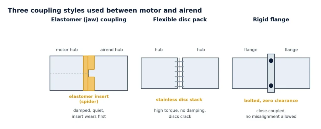
Short answer: most lubricated screw compressors use one of three couplings — an elastomer jaw coupling with a replaceable insert, a flexible disc pack, or a rigid flange on close-coupled machines. If a machine starts knocking or chirping at idle and the noise disappears under load, suspect the insert. If the noise is a metallic rattle that grows with load, suspect alignment or a bearing. Replacing the insert without checking alignment usually means replacing it again within a few months.
The coupling sits between two things that must not touch: the motor shaft turning at 1,500 or 1,800 rpm, and the airend input shaft that carries the full torque of compression. It exists to pass torque and absorb the small errors that no practical assembly can eliminate — a few hundredths of a millimetre of radial offset, a fraction of a degree of angular error, and the thermal growth that happens between a cold start and a hot afternoon. When it fails, the symptom is almost never reported as “coupling”. It arrives as noise, vibration, a snapped insert, or a machine that will not start because the rotor is dragging.
What the coupling has to do, and what it must not do
Three requirements, and they conflict with each other, which is why the choice matters:
- Transmit torque without slip. On a direct-drive screw compressor the coupling is the only torque path. A worn insert can slip under load and generate heat, and the first sign is often a burnt rubber smell rather than a noise.
- Absorb misalignment and shock. Load steps, start torque, and the torsional ripple of the airend all pass through it. An elastomer insert damps that; a rigid flange passes it straight into the bearings.
- Fail safe, or at least fail visibly. A good design wears the insert out before it damages a shaft. A bad one wears a keyway oval and takes the motor shaft with it.
What it must not do is hide a mechanical fault. A coupling that is soft enough to mask a failing airend bearing will also be soft enough to run hot and destroy itself. That is why the diagnosis order in the section below starts with noise and ends with the insert, not the other way round.
Three coupling styles found on screw compressors
Before ordering anything, identify what is on the machine. The visual difference is obvious once the guard is off, and it decides both the failure mode and the spare part you need.
| Style | How it looks | Typical use | How it fails |
|---|---|---|---|
| Elastomer jaw coupling (spider insert) | Two hubs with cast jaws, a star-shaped polyurethane or NBR insert between them | Small and mid-size screw compressors, the most common arrangement | Insert hardens, cracks at the jaw, then crumbles; light knocking at idle |
| Flexible disc pack | Thin stainless discs bolted in alternating packs between hubs | Larger machines and high-torque direct drives | Discs crack from the bolt holes; metallic tick that rises with load |
| Rigid flange | Two bolted flanges, sometimes with a machined spacer | Close-coupled and gear-drive arrangements where alignment is machined in | No compliance, so the bearings or the shaft take the misalignment |
A fourth arrangement still turns up on older or rebuilt machines: a pin-and-bush coupling with a rubber sleeve. Treat it as an elastomer coupling for diagnosis and expect the sleeve to be the wearing part.
Selection: the five numbers you actually need
Couplings are sold by size, and size is driven by five numbers. Four of them come from measuring the machine, one from the motor nameplate. Without all five, any recommendation is a guess.
| Number | Where it comes from | Why it decides the part |
|---|---|---|
| Motor power and speed | Nameplate: kW and rpm | Sets nominal torque; the insert is rated on torque, not power |
| Bore and keyway, both sides | Measure the motor shaft and the airend input shaft | Hubs are bored to order; a motor swap often changes one side only |
| Shaft gap between hubs | Feeler gauge with both shafts locked | Determines hub length and insert thickness; wrong gap pre-loads the insert |
| Insert hardness | Supplied shore grade: 80A, 92A, 95A, or Hytrel-type | Too soft and it runs hot; too hard and it transmits shock to the bearings |
| Guard and coupling OD | Measure the largest hub diameter | Larger hubs will not clear a tight guard on compact machines |
One practical note from the field: when a machine has been re-motored, the airend side is usually original and the motor side is new. The coupling ordered from the compressor model alone is then wrong on one hub. Measure both sides, every time.
Alignment tolerances that stop repeat failures
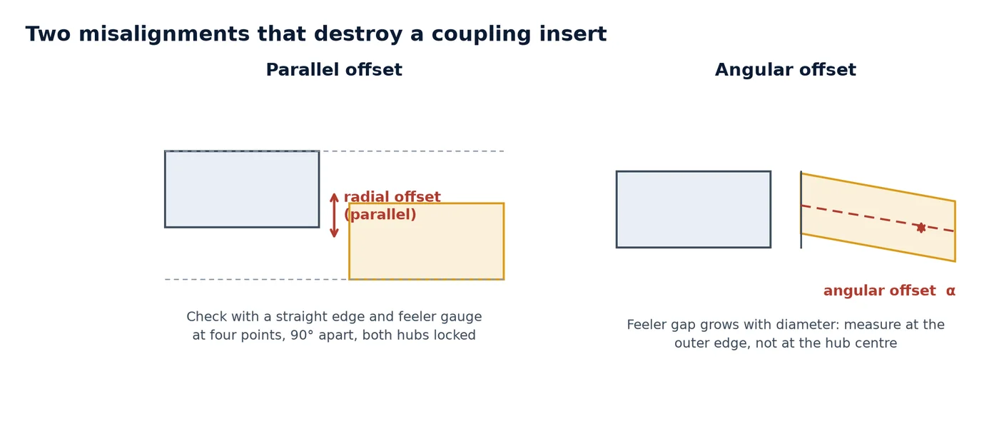
An elastomer insert tolerates misalignment, but it converts that tolerance into heat. The accepted practice is to align to a fraction of the coupling’s rated capacity, so that thermal growth during the first hour of running lands the machine inside the window rather than at the edge of it.
| Check | Method | Working target |
|---|---|---|
| Parallel (radial) offset | Straight edge plus feeler gauge, four points 90° apart, or dial indicator on both hubs | 0.05–0.10 mm, and never more than half the coupling’s rated value |
| Angular offset | Feeler gap at the outer diameter, measured at 0° and 180° | Gap difference under 0.05 mm across the hub face |
| Shaft gap | Feeler gauge, both shafts locked | Within the coupling drawing, typically 1–4 mm |
| Soft foot | Loosen one motor foot bolt at a time and watch a dial indicator | Under 0.05 mm at any foot; shim rather than over-torque |
Align cold, then re-check hot after the machine has run to stabilising temperature. On a machine mounted on a steel skid in a hot room, the motor feet and the airend feet do not grow by the same amount, and the difference shows up as an angular error that was not there at assembly.
Noise and vibration: reading the symptom before stripping
Coupling complaints arrive as sounds. The table below maps the sound to the likely cause and, more importantly, to the check that confirms it. A technician who skips this step usually replaces a good insert and leaves the real fault in place.
| What you hear or feel | Likely cause | Confirmation | Action |
|---|---|---|---|
| Light knocking at idle, quiet under load | Insert worn or hardened; jaws contacting | Guard off, rotate by hand, look for jaw contact marks | Replace insert, then check alignment |
| Metallic tick that grows with load | Disc pack cracking, or loose coupling bolts | Torque check on the disc bolts; dye penetrant on discs | Replace disc pack as a set, new bolts |
| High-frequency squeal, hot hub | Insert slipping, severe misalignment | Infrared check: hub temperature well above ambient | Stop the machine; realign and replace insert |
| Rubber dust inside the guard | Insert rubbing, offset beyond rating | Measure parallel and angular offset | Realign; check motor and airend mounts |
| Vibration at 1× running speed | Imbalance or bent shaft, not the coupling | Vibration reading before and after decoupling | Investigate rotor or motor, not the insert |
| Machine will not turn by hand | Seized airend bearing or rotor contact | Split the coupling, turn each side separately | Stop; airend work, not a coupling job |
That last row saves machines. A coupling replaced on a machine with a failing airend bearing will fail again within weeks, and the second failure usually takes the shaft with it.
Replacement sequence
The order matters, because two of the steps are checks that cannot be done afterwards.
- Lock out and isolate. Discharge the receiver, confirm zero pressure, and lock the isolator. A screw compressor can restart remotely from a controller schedule.
- Record before you strip. Photograph the coupling, note the shaft gap, and take a vibration or temperature reading if you have the instrument. This is your baseline for the alignment check.
- Split the coupling and test both sides. Turn the motor by hand, then the airend. Any roughness on the airend side is a bearing question, not a coupling question.
- Inspect the hubs and keyways. A polished or oval keyway means the insert has been slipping for a long time. Replace the hub, not just the insert.
- Fit the new insert and set the shaft gap. Use the coupling drawing; do not guess from the old part, which may have been wrong to begin with.
- Align cold, then verify hot. Run to stabilising temperature, shut down, and re-check the angular gap. Record what you find.
- Refit the guard properly. A guard that rubs creates a noise that will be misdiagnosed as a coupling failure next month.
Why couplings fail early, and what to fix first
When a coupling fails well inside its expected life, one of these five causes is almost always behind it. Fixing the coupling without fixing the cause is how a machine ends up with three inserts in one year.
- Misalignment after a motor replacement. The most common single cause. New motor, old shims, no realignment.
- Wrong insert hardness. A hard insert fitted to stop a knock transmits shock into the airend bearings, and the noise comes back louder.
- Soft foot or a cracked skid. The machine moves when it warms up, so the alignment you set cold is gone by mid-morning.
- Seized or dry airend bearing. The coupling becomes the weakest link in a chain that is already overloaded.
- Heat and oil mist in the enclosure. Polyurethane hardens with age and temperature; an insert in a hot, oily enclosure ages faster than the hours suggest.
The airend itself is covered in this guide to the compressor air end, and the broader symptom map is in screw air compressor troubleshooting. If the machine is being reassembled from parts, the layout in what makes up a rotary screw air compressor is a useful reference for what sits either side of the coupling.
Stock and inspection interval
For a service operation, the coupling is one of the few parts where holding stock genuinely changes the outcome: a worn insert found at a routine service is a low-cost fix, while the same insert found after it has failed on a Saturday is an emergency. A practical minimum:
- Inserts for the two or three coupling sizes that cover most of the installed base, in the standard hardness for each.
- Complete coupling assemblies for the most common models, so a damaged hub does not become a week of downtime.
- Disc packs and bolt sets where disc couplings are used — discs are replaced as a set, never individually.
- Shim packs and a dial indicator. Alignment tooling is cheaper than any coupling.
Inspection interval: check the coupling at every oil change on machines above 45 kW, and at every second service on smaller units. On a machine that has had a motor replaced, check it again after the first 100 hours — that is when a cold alignment error shows up as rubber dust.
Frequently asked questions
Can I run a compressor with a cracked coupling insert?
No. A cracked insert has already lost its torque capacity and the jaws are now transmitting load metal to metal. Beyond the damage to the hubs, the debris goes into the guard and the enclosure, and the noise masks a bearing fault that may be the real cause. Stop the machine.
How do I know whether the noise is the coupling or the airend?
Split the coupling and turn each side by hand. If the airend side is rough, tight, or has detectable play, the noise is not the coupling. If both sides turn freely and smoothly, and the noise only appears with the coupling fitted, the insert or the alignment is the cause.
Is a harder insert better because it lasts longer?
No. Harder inserts transmit more shock and vibration into the airend and motor bearings, and they tolerate less misalignment. The correct hardness is the one specified for the coupling size and the torque of the drive, not the hardest one available.
How often should the coupling be realigned?
After any motor replacement, after any work that moves the motor or the airend on its mounts, and whenever an insert has failed. Otherwise, check alignment at the annual service. A machine that needed realignment once should be checked again after 100 hours of running.
These answers cover the common cases on lubricated screw compressors. Machine-specific limits always come from the manual of the unit in front of you.
Need the right coupling for a machine?
Send us the motor nameplate, the bore and keyway on both shafts, the shaft gap and a photo of the coupling with the guard off. We will identify the style and match the insert or the complete assembly to the drive.