
VFD vs Fixed-Speed Screw Compressors: Which Parts Are Not Interchangeable
Short answer: a variable speed (VFD) screw compressor and a fixed-speed machine of the same size share the airend, the separator tank and much of the pipework — but they are not the same machine, and eight part groups cannot be swapped between them: the controller, the pressure transducer, the drive motor, the motor cabling, the intake valve, the cooling fan, the oil circuit (pump and minimum pressure valve setting), and the airend itself below its minimum speed.
Mixing them does not usually stop the machine dead. It produces a compressor that runs, holds pressure, and quietly loses capacity, overheats at low speed, or eats bearings. This article explains what a VFD actually changes mechanically, which parts must stay with their drive type, and what to check before converting a fixed-speed unit.
What a VFD changes physically, not just electrically
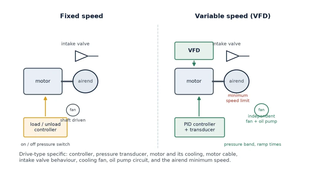
A fixed-speed compressor controls capacity by loading and unloading: the motor runs at line frequency, the intake valve opens or closes, and the machine alternates between full flow and no flow. A VFD machine keeps the intake valve largely open and varies the motor speed instead, so flow follows demand continuously.
Three physical consequences follow, and every part decision comes from them:
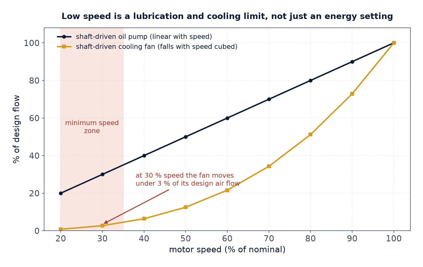
- Speed falls below design point. A VFD might run at 30 % of nominal speed. Oil flow from a shaft-driven oil pump falls with speed, the shaft-mounted fan loses almost all of its cooling effect, and the airend’s bearings get less oil at exactly the moment the oil is hottest.
- Torque stays roughly constant. Below base speed the drive is a constant-torque load, so current stays high while speed drops. Motor heating per unit of airflow rises.
- Pressure is controlled in a loop. The controller needs a continuous pressure signal and a speed command, not a switch contact. This is why the control layer changes completely.
Parts that must not be swapped between the two types
The table below is the practical answer for anyone maintaining a mixed fleet or sourcing spares. “Same part” means the part number crosses over; “different” means it must match the drive type even if the thread, flange or mounting looks identical.
| Part group | Fixed-speed version | VFD version | If you mix them |
|---|---|---|---|
| Controller / PLC | Load-unload logic, digital outputs | PID pressure loop, analogue or bus speed command, minimum-speed limit | No speed regulation, drive alarms, or the machine hunts |
| Pressure sensor | Pressure switch, on/off | Analogue transmitter, 4–20 mA or 0–10 V | Loop unstable or permanently at minimum speed |
| Drive motor | Standard induction motor, shaft-mounted fan | Inverter-duty insulation, independent cooling fan, insulated bearings on larger frames | Winding failure, bearing currents, overheating at low speed |
| Motor cable | Standard 3-core plus earth | Shielded VFD cable, PE bonding both ends, output filter on long runs | Reflected-wave surges at the motor terminals, EMC faults on site electronics |
| Intake valve | Open/close with a loading solenoid | Often a proportional or modulating valve, held near open | Speed and valve fight each other; pressure oscillates |
| Cooling fan | Shaft-driven, speed follows the motor | Independent electric fan, thermostat or inverter controlled | No cooling at 30 % speed; discharge temperature climbs |
| Oil pump / lubrication | Shaft-driven pump, adequate above base speed | Independent pump or a circuit that keeps pressure at minimum speed | Bearing starvation at low speed, oil temperature spikes |
| Airend | Rated for one speed and one tip speed | Minimum speed limit set by bearing lubrication and rotor sealing | Rotor contact, seal wear, or oil not reaching the discharge end |
The control layer: where most “it should work” projects fail
Retrofitting a VFD onto a fixed-speed controller without changing the control layer gives you a compressor that runs at one speed most of the time. The reason is simple: the original controller sees receiver pressure through an on/off switch. It has no way to express “run a little slower”.
A proper VFD control layer needs four things:
- A continuous pressure signal at the discharge or receiver, with the transducer range matched to the working pressure. A 16 bar transmitter on an 8 bar machine wastes most of its resolution.
- A pressure band, not a setpoint. Typically a band of 0.3–0.6 bar; too narrow and the drive hunts, too wide and pressure swings reach the tools.
- A minimum speed limit taken from the airend manufacturer, not from the drive’s capability. Below it, oil flow and rotor sealing degrade.
- Ramp times that respect the drive and the process. A fast ramp on a constant-torque load trips on overcurrent; a very slow ramp lets pressure sag before speed catches up.
Our article on PLC controllers in screw compressor systems covers the signal side in more detail, and the controller range shows what a machine-specific unit looks like.
Lubrication and cooling at low speed: the real mechanical limit
Speed reduction is often described as an energy measure. Mechanically it is a lubrication problem. At 30 % speed:
- a shaft-driven oil pump delivers roughly 30 % of its design flow;
- a shaft-driven fan delivers less than 15 % of its design air flow, because fan flow falls faster than speed;
- oil residence time in the separator tank goes up, which is good for separation but increases the chance of condensate staying in the oil.
That combination is why VFD machines either drive the fan and the oil pump independently, or enforce a minimum speed high enough that the shaft-driven versions still work. If a machine has been converted and the discharge temperature rises whenever it runs slowly, the fan is usually the first part to change, then the oil circuit.
The minimum pressure valve belongs here too. Its setting determines separator tank pressure, and separator efficiency depends on that pressure. On a VFD machine running at low flow, the valve is doing more work than on a fixed-speed machine, and a soft spring shows up as oil carryover at low demand — a symptom that looks like a failed separator element and is not. The mechanical detail is in our guide to the sight glass, return check valve and minimum pressure valve.
Electrical side: motor, cable, and what the drive does to them
A VFD does not deliver a sine wave. It delivers a pulse train with fast edges, and those edges arrive at the motor terminals as voltage spikes that can reach twice the DC bus voltage on long cable runs. Three practical consequences:
- The motor must be inverter-rated. Standard motors often survive, but insulation stress, plus heating from the harmonic content, shortens winding life — especially on machines that spend hours at low speed with a shaft-mounted fan moving almost no air.
- Bearing currents need a path. On larger frames, a common-mode voltage drives current through the bearings and erodes the raceway. Insulated bearings on the non-drive end, or a shaft grounding ring, are the standard fix.
- The cable is part of the design. Shielded cable with the shield bonded at both ends, a separate earth conductor, and an output filter or reactor on long runs. Screens and instrumentation sharing a tray with unshielded motor cable is a classic source of nuisance faults.
None of this appears on a parts list, which is exactly why retrofits that copy the mechanical bill of materials fail on the electrical side.
Retrofit checklist before you convert a fixed-speed machine
If the goal is to run an existing fixed-speed unit on a VFD, work through this list before buying anything. Any “no” is a design change, not a wiring change.
| Check | Requirement |
|---|---|
| Airend minimum speed | Documented by the airend maker; below it, do not go |
| Oil supply at minimum speed | Pressure and flow verified, or an independent pump fitted |
| Cooling at minimum speed | Independent fan or variable fan drive |
| Motor insulation and cooling | Inverter duty, independent fan, bearing protection |
| Controller capability | PID loop, analogue or bus output, minimum-speed parameter |
| Sensor type | Continuous transmitter, correct range |
| Cable and earthing | Shielded motor cable, filter on long runs, single-point signal earth |
| Intake valve behaviour | Held open, or modulating with a defined relationship to speed |
| Blowdown and MPV | Correct setting for the pressure band, seat holding |
Spare parts strategy for a mixed fleet
Plants that run both types usually hold too many of the wrong spares. Two rules cut that down:
- Share the wet end, separate the control end. Elements, filters, valves and sensors that carry no control logic can often be common across both types for the same platform. Controllers, transducers and drive parameters cannot, even when the connectors match.
- Tag every part with the drive type. A filter element that fits both is fine; a controller that fits both physically is a trap. Put the drive type on the bin label, not just the machine serial number in a spreadsheet.
For a mixed fleet, the parts most worth stocking per drive type are the control layer and the cooling side: controller, pressure transducer, fan motor, and for VFD units the drive’s cooling fan and filter mats. Mechanical parts can wait for a planned order; a controller cannot.
If you are unsure which variant a part number belongs to, the sensor and transducer range and the troubleshooting map are a good starting point, and the air filter range shows how the same platform shares its wet-end parts across drive types.
Frequently asked questions
Can I put a VFD on an existing fixed-speed screw compressor?
Sometimes, but it is a re-design, not an add-on. The airend minimum speed, oil supply at low speed, cooling fan, motor insulation and the controller’s ability to run a pressure loop all have to be resolved. A conversion that only adds a drive usually ends up running at fixed speed with extra losses, or overheating at low load.
Is the airend the same on both types?
Often it is the same casting and rotor set on the same platform, but the minimum speed limit and sometimes the bearing lubrication arrangement differ. The VFD version is rated to run slowly without losing oil film or rotor sealing. Fitting a VFD to an airend with no documented minimum speed is where bearing damage starts.
Why does my VFD compressor use more oil than the fixed-speed one next to it?
At low speed the separator tank sees lower pressure and lower velocity. If the minimum pressure valve setting is soft or the return check valve orifice is restricted, oil leaves with the air. Check the pressure the tank holds at minimum demand before blaming the element.
Do VFD machines need a different oil?
Not necessarily a different grade, but they place different demands on it: longer residence time in the tank, more condensate exposure at part load, and lower oil flow at low speed. Follow the machine manual’s viscosity and change interval, and sample the oil rather than extending intervals by habit.
What fails first when a fixed-speed controller is used on a VFD machine?
The drive, through repeated overcurrent or overvoltage trips, because the controller commands load and unload instead of a speed ramp. After that, contactors and the intake valve solenoid wear out from excessive cycling. The mechanical parts are usually the last to show the problem.
Do both types use the same intake valve?
Rarely the same behaviour. Fixed-speed machines use an open/close valve driven by a loading solenoid; VFD machines often hold the valve nearly open and modulate speed, or use a proportional valve. A swap can produce pressure oscillation because speed and valve are both trying to control the same variable.
These answers cover the common cases. Machine-specific limits always come from the manual of the unit in front of you.
Matching parts to the right drive type
Tell us the model, the drive type and the part you need — we will confirm whether the fixed-speed and variable-speed variants share a part number before you order.