Auto Drain For Air Compressor


AKZL-13/14

The figure shows that the condensate flows into the condensate drain through inlet ① and accumulates in the chamber ②. The capacitance sensor ③ continuously detects the liquid level and signals the control part when the liquid fills the chamber. Then, pilot valve ④ is activated, and diaphragm valve ⑤ opens drain port ⑥ to discharge condensate. When the condensate in the condensate drain is drained, the drain port will be closed quickly, which will not cause the loss of compressed air.

1. The inlet pipe ①should be continuously inclined downward > 1% to make the condensate flow into the water storage tank,
2. The minimum diameter of input pipe② and connector ④is 1 / 2” (inner diameter > 15mm) and large pipe shall be selected as far as possible to reduce resistance
3. Small filter and U-shaped pipeline can not be installed before the inlet ③ , which will affect the self flow performance of condensate.
4. Only large diameter ball valve or gate valve or butterfly valve can be used at the inlet④, and sufficient opening degree shall be ensured.
5. The minimum working pressure of water storage tank⑤ is 0.8bar or 1.6bar (see the label for details).
6. Drainage pressure hose ⑥should be selected as far as possible to facilitate installation.
7. The minimum pressure increase of 0.1bar is required for every 1m rise of the drainage outlet pipe⑦, and the rising section of the output end is not more than 5m!
8. The minimum diameter of the drainage header⑧ is 1 “, and 1% downward tilt can reduce the drainage resistance.
9. The spare nozzle⑨ can be used for vertical installation or large diameter pipe, and can also be used as return pipe.
10. The drain outlet⑩ can be installed with ball valve as manual sewage discharge or as heater installation port.
Remarks: when the condensate automatically flows into the water storage tank or the return
producing PET plastic containers and bottles in all shapes.
| Model | AKZL-13 | AKZL-14 |
| Inlet port size | 2*G1/2″ | 2*G1/2″+ G3/4″ |
| outlet port size | G1/2″ | G1/2″ |
| WorKing tempreture | (1-60)℃ | (1-60)℃ |
| MAX air compressor | 30m³/min | 130m³/min |
| Max freeze dryer | 60m³/min | 260m³/min |
| Max filter | 300m³/min | 1300m³/min |
| Voltage | 220VAC/110VAC/DC24V | 220AC/110AC/DC24V |
| Working pressure | 0.8-16Bar | 0.8-16Bar |


TIMER AUTO DRAIN VALVE
| Interval time(OFF time) | 0.5-45 minutes |
| Discharge Time(ON time) | 0.5-10 Seconds |
| Timer Manual TEST switch | Yes, micro switch |
| Voltage | 24-240V AC/DC 50/60Hz |
| Current Consumption | 4mA |
| Ambient Temperature | -40-60degree Celsius |
| Protection grade | IP65 |
| Time shell material | ABS Plastic FR Grade |
| Timer Connection | DIN43650A |
| Timer Indicators | On/off |


METAL CUP DRAIN VLAVE

Pneumatic automatic drain valve can be used for compressed air equipment, the condensate water in the pipeline can be discharged out of the system automatically and keep the compressed air dry clean.
USE FOR: air compressor, gasholder, filter, pneumatic system.
| Model | AKD402-02 | AKD402-03 | AKD402-04 |
| Ensured Pressure Resistance | 1.5MPa | ||
| Operating Pressure Range | 0.15~1.0MPa | ||
| Ambient and Fluid Temperature | 5~60ºC | ||
| Port Size | G1/4 | G3/8 | G1/2 |
| Drain Port Size | G1/8 | ||
| Drain Status | Normal Open Type | ||
| Working Medium | Compressed Air | ||


BALL DRAIN VALVE
- The filter housing is made of aluminum alloy by die-casting and has a compact structure to ensure safe use.
- All housings are cleaned, degreased, and specially anti-corrosion treated before spraying to improve durability and applied to offshore platform operations.
- The precise threaded interface makes installation and maintenance more accessible and more convenient.
- All housings tested under working pressure 32bar for 96 hours, and the maximum burst pressure is 105bar.
- Under the working condition of 1.5-80 ºC and pressure 16 bar, the body is guaranteed 15 years, and the service life of the Filter Element is 6000-8000 hours.
Product Name | Float Type Air Compressor Drain Valve with Automatic Discharge | ||
Type | Ball float type | ||
Condensed water inlet and outlet connection | 1/2″ BSP | ||
Max. pressure | 16bar | ||
Max. temperature | 100 ℃ | ||
Maximum discharge capacity | 500L/Hour | ||
Certification | CE/ISO9001 | ||
Which type of auto drain fits your system
Four families cover almost every installation. The right one depends on how much condensate the point makes, whether compressed air is expensive for you, and whether power is available at the drain point.
| Type | How it opens | Air loss | Best for | Watch out for |
|---|---|---|---|---|
| Level-sensing (zero-loss) AKZL-13 / AKZL-14 |
A capacitance probe reads the level and pilots the diaphragm valve open | Negligible — only liquid leaves the system | Receivers, dryers and filters where compressed air is expensive, or where the condensate load is high | Keep the strainer clean; inlet pipe 1/2″ or larger |
| Timer solenoid timer auto drain valve |
An electronic timer energises the solenoid on a set cycle | A short pulse of air on every cycle | Steady condensate load; the simplest choice for a receiver or a dryer | A long ON time wastes air — shorten the OFF time instead |
| Float / cup type AKD402 |
A float rises with the condensate and opens the valve, then closes as the cup empties | No continuous air loss | Varying condensate load, or points with no power supply — filters, drip legs | Oil sludge can foul the seat — clean periodically |
| Manual ball valve ball drain valve |
The operator opens it on each shift | None while closed | Isolation, low-traffic systems, drain points that must be checked by hand | Depends on people — the usual reason water reaches the dryer |
Sizing the drain and where the drains go

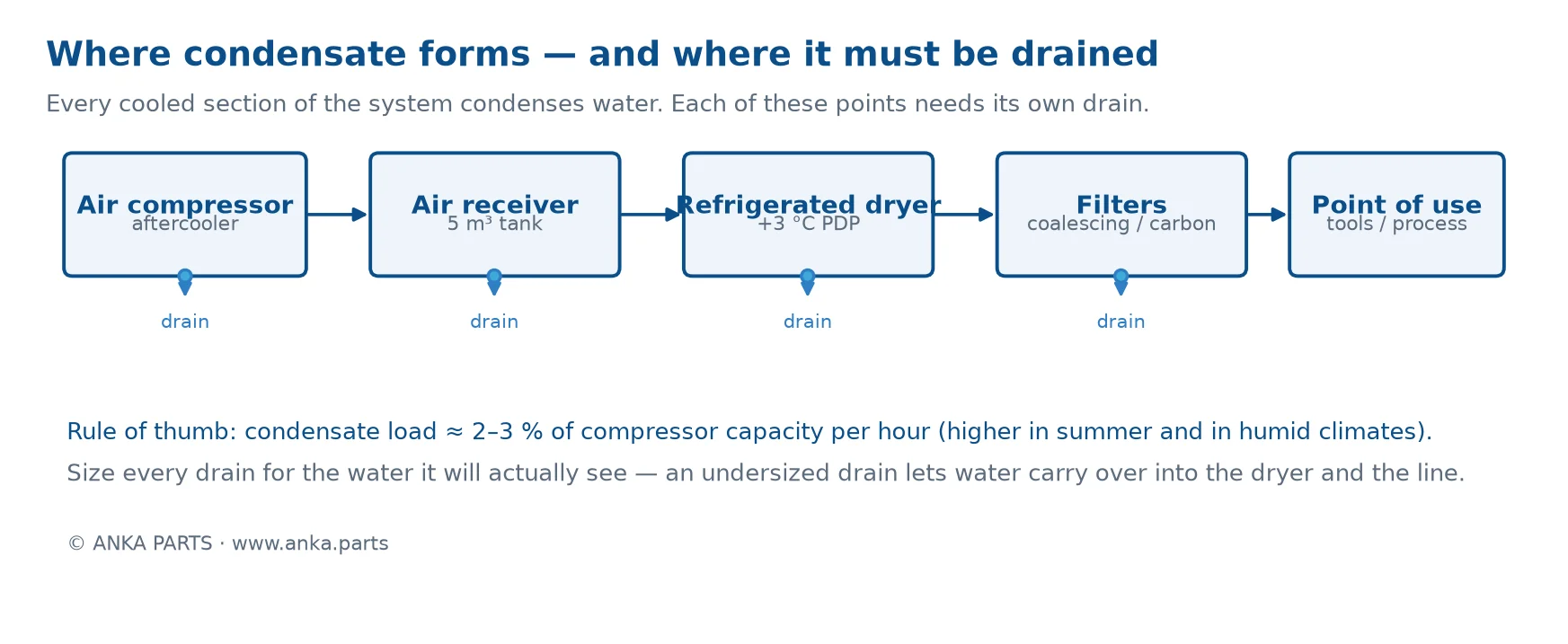
Every low point needs its own drain. Condensate forms wherever compressed air is cooled — the aftercooler, the receiver, the refrigerated dryer and the filters. Fit a drain to each of them; one drain at the end of the line does not protect the equipment upstream.
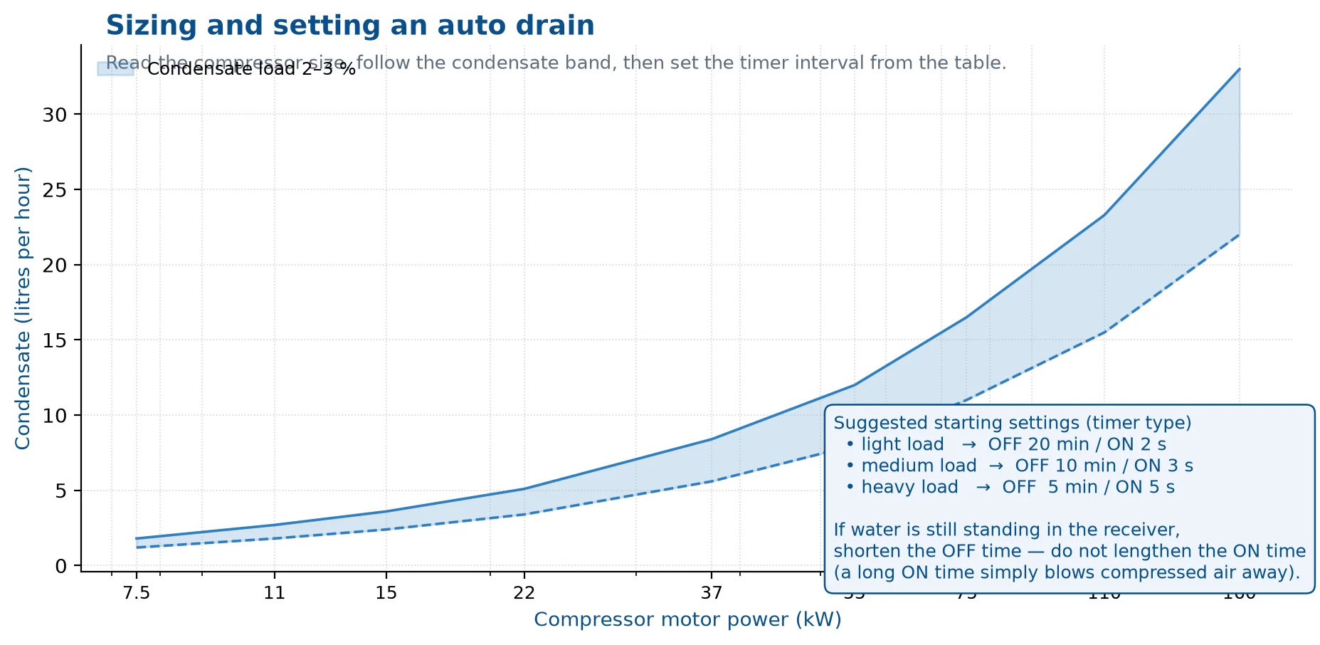
- Estimate the load first. Expect roughly 2–3 % of the compressor capacity per hour as liquid condensate; more in summer, in humid climates and with an unlagged receiver.
- Inlet pipe must run continuously downhill at more than 1 % slope, with a minimum bore of 1/2″ (inner diameter ≥ 15 mm) — larger is better, it reduces the risk of sludge blocking the line.
- Do not fit a small filter or a U-trap ahead of the inlet. It looks tidy but it slows the gravity flow and the drain then never sees the water.
- Discharge to an oil–water separator, not to the floor drain: the condensate carries compressor oil and has to be separated before disposal.
- Test it. Most timer units have a manual TEST button — press it at the end of each shift and watch that the drain actually discharges.
Setting a timer drain

A timer drain is only as good as its settings. Start from the chart below, then correct by observation: if water is still standing in the receiver when you open it, shorten the OFF time. Lengthening the ON time is the wrong fix — it discharges more compressed air, not more water.
Our timer drains adjust from 0.5–45 minutes OFF and 0.5–10 seconds ON, work on 24–240 V AC/DC, draw 4 mA, and are rated IP65 with a manual TEST switch.
Troubleshooting an auto drain
Most drain problems are installation or setting problems rather than a failed valve. Work through these four before replacing anything.
| Symptom | Usual cause | What to do |
|---|---|---|
| Water still in the receiver | OFF interval too long, strainer blocked, inlet bore too small, or the pipe slopes back towards the tank | Shorten the interval, clean the strainer, re-pipe at ≥ 1/2″ with a continuous fall |
| Drain never opens | No supply voltage, failed timer, blocked pilot orifice or sensor fouled with oil | Check voltage at the coil, press TEST, clean the pilot orifice and the probe |
| Air blowing continuously | Debris stuck in the seat, or the diaphragm is worn | Isolate, flush the seat, fit a repair kit or replace the diaphragm |
| Drain blocks with sludge | Heavy oil carry-over from a worn separator, or a long horizontal run | Fix the separator first, then consider a motorised ball valve which shears through sludge |
Auto drain FAQ
How often should an auto drain open?
It depends on the condensate load, not on a fixed rule. Start at OFF 10 min / ON 3 s for a medium load and watch the receiver for a week: standing water means shorter OFF, no water and frequent cycling means longer OFF. The ON time only needs to be long enough to empty the chamber.
Can the same drain be used at 16 bar?
Our AKZL-13/14 level-sensing drains are rated 0.8–16 bar, and the AKD402 float type works from 0.15–1.0 MPa (1.5–10 bar). Check the rating against your maximum working pressure before ordering — a drain sized for 10 bar should not go on a 16 bar receiver.
Do I need a drain on the dryer as well as on the tank?
Yes. The dryer removes far more water than the receiver, and that water has to leave somewhere. A dryer without its own drain simply passes the condensate downstream to the filters and the process.
What connection size do the drains use, and what is the maximum discharge?
The common size is 1/2″ BSP on both inlet and outlet, with a maximum discharge capacity around 500 L/hour and a maximum temperature of 100 °C. If your condensate load is higher, use a larger model or split the drainage into two points.
Which type of auto drain suits your system
Draining condensate automatically protects the receiver, the dryer and the tools downstream. Which type you fit depends on how much water the system makes and how the drain will be controlled:
- Timer auto drain (AKZL-13/14) — opens on a set cycle. The simplest choice for a receiver or dryer where condensate volume is steady.
- Metal cup drain valve — a float design that discharges whenever the cup fills. Useful where condensate volume varies and a fixed timer would either waste air or leave water standing.
- Ball drain valve — a manual valve for isolation and for drain points that an operator checks each shift.
Setting and sizing an auto drain
- Match the drain to the line: this range uses a 1/2″ BSP connection, with a maximum working pressure of 16 bar, a maximum temperature of 100 °C and a maximum discharge capacity of 500 L/hour.
- Start with a short interval and adjust: if water is still standing in the receiver, shorten the interval rather than lengthening the opening time.
- An opening time that is too long wastes compressed air; one that is too short leaves condensate to carry over into the dryer.
- Protect the drain from freezing in winter — a frozen drain is the most common reason water reaches the dryer.
- Keep the pilot filter clean and fit a strainer where dirt is heavy, so debris cannot hold the valve open.
FAQ
Do I still need a manual drain if I fit an auto drain?
Keep one at the low point as a backup and for draining during service. An auto drain that fails closed is silent — you notice it only when water reaches the dryer or the tools.
Can an auto drain be used on a 16 bar system?
Yes. This range is rated to 16 bar and the timer, cup and ball types share the same connection. Check the working pressure of your receiver rather than the nominal rating of the compressor.
Where should the drain be fitted?
At the lowest point of the receiver or the separator, with enough clearance to remove the cup or the timer head for service.
Where condensate collects in a compressed air system
Water enters with the intake air and condenses wherever the air cools. In practice that means several drain points, and a system usually needs more than one:
- Receiver / air tank — the largest volume of liquid water, and the point most people drain first.
- Aftercooler and oil separator — where the first big temperature drop happens.
- Refrigerated or desiccant dryer — the dryer deliberately condenses water, so its trap has to discharge reliably.
- Filters and drip legs — line filters, precision filters and low points in the piping.
If one of them is missed, water is carried downstream and shows up as emulsion in the oil, rust in the pipe or wet tools. Fit a drain wherever water can settle, not only at the tank.
Auto drain types compared
| Type | How it opens | Compressed air used | Best for | Watch out for |
|---|---|---|---|---|
| Timer (electronic), AKZL-13/14 | On a set cycle: opening time and interval are adjustable | Fixed by the setting; wastes air if the interval is set too short | Steady condensate load — receiver, dryer, filter | Does not react to load changes, so the setting has to be reviewed summer and winter |
| Metal cup / float | A mechanical float lifts when the cup fills | Only while it is discharging | Variable load, or where no power supply is available | Dirt on the seat holds it open; fit a strainer upstream |
| Level sensing | A sensor detects water and opens for a set time | Lowest of the automatic types | Large receivers and dryers where air loss matters | Oil emulsion on the sensor gives false readings |
| Ball valve (manual) | The operator opens it | Only if it is left open | Isolation, low points checked each shift, backup drain | Forgotten — the most common cause of water carry-over |
Setting the timer: cycle time and air loss
A timer drain gives up compressed air for the whole opening time, so the setting trades water removal against air loss. The air lost is simply the fraction of time the valve is open: air loss ≈ opening time ÷ cycle time. A drain that opens for 5 seconds every 5 minutes is open 1.7% of the time; opening for 10 seconds on the same cycle doubles that.
- Start from the condensate volume, not from habit: drain the receiver manually for one shift, measure the water, then set the interval so the drain discharges roughly that volume per shift.
- If water is still standing, shorten the interval first. A longer opening time mostly wastes air once the cup is empty.
- In summer, or on a machine with a wet aftercooler, halve the interval. In winter, check the drain and its discharge line for freezing.
- Fit a strainer or a pilot filter ahead of the valve: scale and rust are what stop a timer drain from closing again.
Installation checklist
- Mount at the lowest point of the receiver or separator, with room to remove the cup or the timer head for service.
- Use the connection the drain is built for — this range is 1/2″ BSP — and support the valve so the thread is not carrying its weight.
- Discharge to a collection point, not onto the floor: condensate carries oil and should pass an oil-water separator before disposal.
- Specify the coil voltage before ordering (220V and 24V are both common) and keep the electrical line away from the compressor power wiring.
- Write the setting on the machine so the next service does not have to guess it.
Troubleshooting an auto drain
| Symptom | Likely cause | What to do |
|---|---|---|
| Continuous blowing, air leaking from the drain | Dirt on the seat, a worn seal, or a timer stuck in the open position | Clean the seat, fit a strainer upstream, replace the seal kit |
| No discharge, water standing in the receiver | Blocked strainer, frozen line, failed coil or a stuck float | Clean the strainer, check the coil with a meter, thaw and insulate the line |
| Water reaching the dryer or the tools | Interval too long for the load, or a drain point with no valve at all | Shorten the interval and add drains at filters and drip legs |
| Emulsion in the oil | Condensate carry-over from a drain that only works intermittently | Fix the drain first, then change the oil and the oil filter |
| Drain triggering erratically | Voltage drop, moisture inside the timer head, contaminated pilot air | Check the supply voltage and the pilot filter; replace the timer head if water has entered it |
Related parts
An auto drain is one part of keeping condensate out of the line. It works together with the AK series precision filters, the AH series filters, the oil-gas separator element and the oil filter. If you are matching a drain to an existing installation, send us the connection size, the working pressure and the coil voltage and we will confirm the type.